Designing the door to the microwave is turning out to be a bit more fiddly than I hoped. This is a combination of mechanicals being new to me and regulatory concerns about keeping the dangerous radiation in the box.
The criteria isn’t too complex, discovering that non-Australian standards are a touch more expansive was an unpleasant surprise though:
Must open to allow foods in and out.
Must comply with Aus, US & EU standards.
Must provide RF seal when shut (no cooking bystanders).
Must have double interlock to prevent operation when open.
Must be durable and maintain seal through lifespan.
Must indicate when sealed to allow operation.
Must provide mechanism to open/lock.
Should allow viewing of food.
Standards
I was a bit annoyed to discover the US FDA standard Part 1030 in working through the door design. The Australian microwave standards simply specify a maximum allowed external radiation level. The US standards cover the radiation level, door interlocks and also mandate the presence of a user manual, service manual and a pair of warning stickers. The EU standards further proscribe durability tests.
According to a completely reputable source I actually only have to comply with the Australian regulations, if I ship a product to the US then the person buying it is considered the importer and are responsible for the local compliance. This is a touch dodgy, even for me. My plan is to comply and certify with the relevant Australian, US and EU (IEC) standards for a domestic microwave. As most countries have formally harmonized with the IEC standard or based their standard off the US or Europe standards I should actually comply with basically everyone worldwide. I am not going to pay for hundreds of certification marks and the documentation required to make it formal though.
Radiation leakage
All the standards specify limits on radiation leakage. During operation a radiation detector is moved around 5cm from the unit and the level must not exceed 1mW/cm². The areas of concern are any holes in the cavity like air holes or the front viewing panel, any seams to ensure they are welded correctly and my biggest concern is the edge around the sides of the door.
Deliberate holes are the easiest issue to handle. Radiation has a wavelength, for a microwave oven this is roughly 120mm. You can do complex maths around radiation holes by treating them as waveguides but it basically boils down to a 120mm wave needs a 120mm hole. As the hole gets smaller than 120mm you get an exponential drop in the radiation slipping through. Often a hole less than 1/4 or 1/10th of the wavelength is approximated as having zero transmission. My Panasonic microwave has holes of 1mm at the front, 2mm on the top and 3mm on the side, all less than 1/40th of the wavelength. I think the small holes are preferred by the manufacturers for their strength rather than due to radiation concerns.
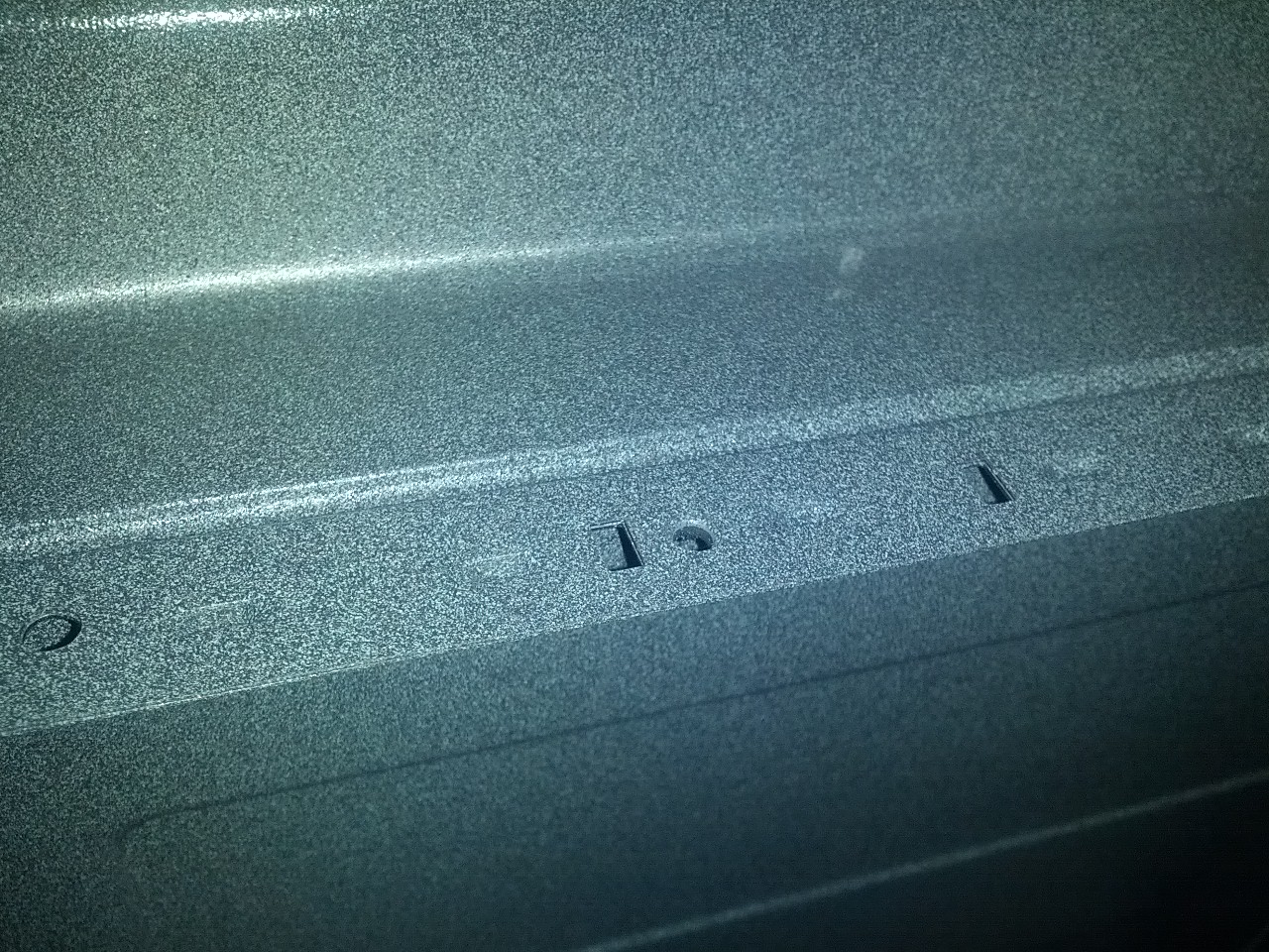
The microwave radiation cavity is going to be made of several sheets of metal welded together. As radiation can slip out a narrow slit just as happily as a gaping hole care has to be taken at the joins to prevent this. My victim microwaves both put a dent in just before the join to block the radiation from reaching the slit. The spot welds they used also seem to involve indentation which would assist in breaking up any slit, the welds are spaced every 22mm. Dents like that are a bit harder with my manufacturing techniques but are possible, I think this one can be solved in consultation with the manufacturer and a little bit of testing.
Panasonic’s RF safe welding join
Panasonic's RF safe welding join
The most concerning issue is the edges of the door. These are nice big slits, just perfect for radiation to spew out of. Looking at the Samsung microwave I think the way this is generally solved is very sneaky and clever. They haven’t followed the obvious solution of trying to create a tight seal, with the Samsung microwave door shut I can see light from a torch shining through, a piece of paper moves without resistance. However if you look closely the aluminium outer frame of the microwave overlaps the door by a few mm. I’ve checked and found this in three microwaves, all different brands. I think what is happening is that the aluminium lip catches the radiation that slips out and limits the amount that gets through. The lip isn’t present on the bottom, so I think they have been differently sneaky there. For the testing of the device it would be reasonable to assume it would be placed a horizontal surface, the manual probably specifies this as the standard operating condition. This position would prevent the detection device being placed 5cm below the microwave door, compliance achieved, problem solved.
Door Interlocks
An interlock is a switch which prevents operation of a device when it is open. For example robots often have a proximity sensor or gate, get too close and the robot immediately shuts down. A common example of this is the automated airport bag drop systems, if you are too close to your bag the conveyor will shut down. Given that a microwave is a touch dangerous it is only sensible that we employ an interlock to prevent operation when the door is open. However US standards require that we take this a fair bit further.
The US Federal Regulations are very specific about what safety interlock must be employed and that special provision must be taken to prevent them from being disabled. Being able to disable an interlock is often a desired feature, the thinking is that if you want to deliberately bypass the safeties then you have chosen to accept the risk and know what you are doing. I assume somebody in the US disabled the interlock on their microwave and got fried, personally I feel they achieved their desired outcome but the regulator obviously felt differently.
The regulations aren’t easy to read, it comes down to this example circuit. Modern microwaves have tweaked it slightly but all follow roughly this pattern. You have three switches, your primary interlock which shuts off power to the system, your secondary or monitor interlock which shorts the unpowered system and a sense switch for the control logic. The combination of these two interlocks means that if either one of them fails or is disabled then the short circuit causes the fuse to blow, as these are small mechanical components this is a common microwave failure point.
There are additional restrictions however, the primary interlock must be designed such that it cannot be deliberately disabled. Specifically a mechanical interlock must be concealed such that it can’t be poked by any body part or straight object, a magnetic interlock can’t be tripped by sticking a magnet against the body of the microwave. Also the primary and monitor interlocks must be mechanically and electrically distinct. The ubiquitous double hook design that every microwave uses makes far more sense with this understanding. A hook is required to meet the concealed requirement and two hooks are required to keep things distinct.
There are opportunities to vary the double hook pattern however. A single hook could be used for the primary interlock with an alternative method used for the other switches. A flexible stick would also meet the criteria if it was guided into a bend. My preference though is for a non-mechanical switch, something more elegant to contrast against the clunky nature of a door. Fortunately there are lots of options. I am leaning towards a magnet despite the restrictions imposed by the standard, I think with a non-magnetic chassis I should be ok as it won’t self-support and there are other ways to skin the cat such as coded magnets.
Durability
The European/International standard is IEC 60335-2-25 ed6.1. I can’t actually find a copy of the document so I might have to buy it. However from the public documentation you can see that it contains the restrictions in the US regulations, with some slight variation, and some additional durability tests. I have found a brief writeup of the durability tests and the news isn’t good. I don’t think passing the tests will be difficult, just need decent hinges. However getting the test house to open and shut the door 100,000 times is going to be expensive. Assuming one second to open the door and one second to close it, that is 56 hours of continuous testing using their 6-DOF robot. The other tests will take another day, this has probably just doubled my testing expenses. I’ll build a basic push/pull robot for my pretesting which could be fun.
Options
Understanding the criteria I now have to design a door.
There are several obvious options, each with their own drawbacks.
I can design a clone of the standard door and make my own. Starting with this one to get it out of the way. The cost of doing this makes it a non-starter. I spoke to the very helpful staff at SK Plastic to understand the costs around injection molding. To build the latch for a microwave door would probably cost roughly $10k-15k for the tool, $1 per part and some other costs for the design and run start etc. At my pricing quantity of 500 units the latch alone would come to roughly $26. The cost of the other larger plastic parts would be higher and the metal screen would either have to be stamped (at least another $10k tooling) or every hold punched individually (several dollars per sheet).
I can buy a door. All the doors are the same, so there is obviously a few companies making these doors. A logical option would be to buy an existing door, either whole or in parts. For example Alibaba has manufacturers offering the door latch, I haven’t enquired as to the price but expect it would be well under $1 per unit. Going half way down this path is difficult, the standard latch means I have to use the matching catches and microswitches with the related durability issues. The latch also dictates the thickness of the door, which pushes again towards plastics as metal would be very heavy. Buying existing outer plastics would result in the microwave having the same appearance as every other microwave, probably looking like the cheap end of the spectrum as that is what is available. Vacuum formed plastic is probably within my price envelope as the setup costs aren’t too bad, I am wary about a heat sensitive plastic in a microwave but apparently PET and HDPE can work.
I can design something new. The big risk here is falling prey to not-invented-here syndrome and a belief that I my design skills are superior to all the major manufacturers combined. However this entire exercise is essentially predicated on that case so I’ll just move on. Doing this will allow me to differentiate the product in a way that is obvious to anyone interacting with it. It will add time and cost to put it all together.
Going forward my plan A is going to be to design from scratch, plan B is to buy in components. Getting half way through a scratch design and then buying in parts where required would probably be a reasonable compromise outcome so blundering forward on my own isn’t a total loss.
Draft design
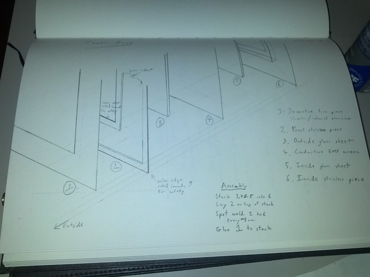
The modern microwave is almost entirely injection molded plastic and stamped steel, both techniques require mass production I can’t rely on. My manufacturing is primarily orientated around bending sheet metal and for the door, glass.
The preliminary design is for a metal and glass sandwich, in my head it is rather elegant. The layers to the sandwich are a metal inner frame, glass plate, metal RF mesh, glass plate, metal outer frame, some trim. Each glass sheet is 2mm thick, the metal 1mm thick and the RF shield 1mm, so the total thickness is just 7mm compared to my Samsung’s 30mm. Being thin won’t just look awesome, it also helps keep my weight down.
As bonus features I should also be able to get the door to open almost 180 degrees and be able to support left handed doors.
I have envisaged that the sandwich will be assembled and then the two metal sheets spot welded to seal the glass in. Then a trim piece of metal glued on to cover the spot welds and pretty it up.
I am yet to settle on the hinges, latch or interlock mechanisms. At the moment I am thinking of them as accessorising for the door. Realistically some trial and error is going to be required for all three of these areas.
Pencil sketch of door sandwich
Pencil sketch of door sandwich
RF Shield
Every microwave I have seen has a solid metal sheet in the front window with circular holes stamped in it. The two microwaves I have measured both have holes roughly 1mm in size. As discussed earlier this is 1/120th of the wavelength and excessively cautious, internal air vent holes are 3mm for example. The pattern is a tradeoff between minimising the metal between the holes, structural strength and ease of cleaning. I think with my door structure the tradeoff isn’t required so I can better optimise the visibility.
A typical guideline for RF shielding is 1/4 of the wavelength allowing holes up to 3cm. Because it is easier to buy I am going to use a square hole, radiation is sneaky and can sneak out on the diagonal so to maintain 1/4 wavelength the square hole must be smaller than 21x21mm.
A wire mesh at 20x20mm is a fairly cheap option and at roughly 75% open area provides better visibility than the existing microwaves. The RF performance will be worse than the existing standard due to the increased hole size and decreased thickness however I think it should be within spec, testing will confirm this before the design is finalised.
If I had sufficient quantity what I really want to do is have a piece of glass manufactured with the metal screen built into the glass. This would significantly reduce complexity by removing the layers and the glass would protect the screen from damage. However doing this would require a special manufacturing rig with associated costs that can only be recovered with large quantities.
Latch
Once closed the door has to stay closed until it is deliberately opened. I have a strong preference for a latch that releases by being pulled on, the push button to open design feels clumsy to me. Again we have options 😃
A hook latch is standard in microwaves. The hook is on the door and hooks into a static hole on the body of the microwave. A spring on the hook keeps it closed until delibrately opened. A slope on the back of the hook allows it to be shut while closed, the hook slides up the latch until it is over then pulls shut. There are two common opening mechanisms, the standard push button works by physically pushing against the hook to raise and released it. The doors you can simply pull open have an oval shaped hook, basically a slope on the inside of the hook allows it to be pulled out much like it is pushed in.
Gravity is an interesting option. By making the door on an angle I can have it naturally sit in the closed position but little force would be required to open it again. This would be cheap but have the downsides of not looking sturdy and not working if the microwave wasn’t flat. Pairing this with a top opening door might work.
Spring loaded hinge is an easy solution. Putting springs into hinge mechanisms is fairly common practice for auto-closing doors, gates or cupboards. The spring hinge can be fitted without much additional work and allows easy operation. I don’t know if an autoclosing door is an advantage or disadvantage.
Magnets are awesome. Magnets are also a possible door latch mechanism, the common stainless steel isn’t magnetic so I would do this by putting a magnet in both the door and body of the microwave. The magnet would help close the door if it was almost closed and keep it closed until tugged open. Best of all I should be able to hide them so it just happens magically.
Closed detection
Both my victim microwaves have three microswitches that get hit by the latch when the door is closed. Two of these are used to implement the standards required interlock system, the third is a low voltage signal to the control circuitry.
The standards require that there be at least two independent detection devices, one of which must be tamper resistant.
Again, there are multiple options.
A hook latch paired with microswitches like every other microwave. Rather boring though.
Directly pushing a microswitch stuck on the surface, probably hiding under a plastic film for cleaning. This is simple, nothing is required on the door and contact is measure directly. It doesn’t meet the tamper resistant requirements but is suitable for a secondary switch.
Magnetic proximity detection works by mounting a permanent magnet on the door and then looking for it. For this to be tamper resistant it can’t be triggered by placing a magnet on the microwave, I think this is free because a stainless steel body shouldn’t be magnetic. This couples nicely with a magnetic closing mechanism.
Light gate detection much like a shop uses a light beam and mirror I can do the same. Requiring a mirror to be mounted on the door fulfills the primary switch requirements. I can probably use polished steel which would be reflective enough to achieve this and with a tiny hole on the body it would be sufficiently magic to be awesome. The downside is that any food or grime that block the mirror would prevent the switch from closing. And being fairly magic like it wouldn’t be obvious which bit of grime was the problem.
A rotation sensor positioned in the hinge would also work. This would complicate the hinge area a bit but would meet all the requirements for the primary switch. One could be placed on the top and bottom to get two independent controls. This would require a microchip for each sensor (ATTiny – yay!) to read the value and control a high voltage relay but we are still in the few dollars price range.
I am publishing my first WordPress theme, Fifteen Twenty. Born out of frustration at the WordPress theme structure when attempting to update the theme of this blog it demonstrates an alternative. This theme is designed as a technical demonstration of structuring a WordPress theme with a single core layout file. As this is an inversion of the standard structure of the default theme Twenty Fifteen I have dubbed it Fifteen Twenty. The appearance, styling and generated html is the same as the original.
WordPress is an open source blogging platform, it is the most popular blogging platform with over 60 million websites using it. To enable all of these websites WordPress has a theme system which allows the user to radically change the appearance of their blog with just a few clicks. Most of these themes are contributed by users but the WordPress team does release a theme every year, this is the default theme and acts as a best practices template for theme designers. The default themes are named after the year, the current one is Twenty Fifteen.
WordPress themes consist of a collection of php template files. WordPress chooses a template based on the type of content being requested, this allows a different template to be used for search results or an audio attachment. The decision is made using the template hierarchy depicted below. WordPress proceeds from left to right until it finds a file which matches the desired pattern, on the far right index.php acts as a catch all for any file types not specially handled.
The advantage of this structure is that it allows for a huge degree of flexibility in the styling. Any content can have a complete different set of styling provided to it and the hierarchy allows for very specific speciality pages to be created.
The disadvantage is that every template requires a duplication of the site structure. Changes such as reordering the HTML structure require the reworking of every single template file, this was exactly the problem I faced when working on this blog’s template Piano Black.
In practice I feel the theme hierarchy structure is a poor design choice as you want to retain the same look a feel across the entire site. This means that the layout is consistent and the variations are typically isolated to the central content pane. Theme authors attempt to reduce the amount of duplication by using a header and footer file which is pulled into each template, this helps to reduce work for minor changes but makes structural alterations even harder.
The alternative technique is to have a single template file which sets the structure of the website. This file then pulls in partial templates based on the content being requested. The partial templates provide a reduced level of flexibility compared to the full template model but are simpler as they do not need to include as much of the site’s structure. The Twenty Fifteen theme actually uses both full and partial templates, the partial templates are used within the full templates to customise different categories of posts.
I do not mean this as an attack or criticism of the WordPress team, the choice was a trade off and they chose the more flexible approach leading to a product far more successful than any I have ever produced. This choice was also made for the initial release in 2003, a different online environment with alternative aesthetic (MySpace) and less use of javascript. They have made a fantastic product and the flexibility built through it allows for novel uses, like mine.
By removing all the custom template files WordPress will always use index.php as a template. As the template is a full php file it can examine the requested content type and pull in the required partial template. This technique uses the WordPress partial include function which enables sub-themes to customise specific partials.
To demonstrate this layout technique I chose to rework the Twenty Fifteen theme as it is designed as a basis for theme authors to work from, which is also my goal. I took each of the template files and pushed the common elements up to index.php converting them into a partial. The files designed to reduce duplication such as header.php, footer.php and sidebar.php were also pushed into index.php. I then set up a demo site using the wptest.io test data and used wget –mirror, HTML tidy, a tiny bit of sed and diff to beat the last bugs out and ensure that the final result was unchanged from the initial Twenty Fifteen design.
In the future I’ll be releasing my updated version of Piano Black, this blog’s theme, with mobile support (responsive layout) and other modernising updates under the hood. I may also make an AngularJS powered demonstration version of Fifteen Twenty for fun.
The fan in my laptop died this week. It has been struggling and groaning noisily along for a while now, occasionally the boot has even failed due to a fan error but a second shot always got through. While I had the system switched off I thought it would be a good idea to blow the dust out and give it a bit of love. It still groans along but now the fan error is consistent. 😦 I have ordered a replacement fan which should arrive next week. In the last six months I have had to swap the battery, hard drive and fan. Maybe my Lenovo is reaching the end of its lifespan, 2008 was a while ago and apparently it doesn’t even run WOW.
Other Other News
In better other news, a friend pointed out that a recent XKCD what if? post is on the topic of microwaves. Because it seems microwaves are awesome.
Screen
I have contacted several suppliers of the Banana Pi and a screen supplier to get price estimates. The screen supplier may be able to fit the touchscreen, which is a bonus, otherwise I have some touchscreen suppliers selected to approach.
The initial Banana Pi pricing is $29 USD in quantities of 500, $34 for samples. I am looking at a seven inch IPS screen which I expect to be roughly $15 and another few bucks for the capacitive touchscreen. So a total bill of roughly $50 USD with no electronic design required, which makes me very happy.
An interesting side note is that both the Raspberry Pi and Banana Pi feature a ribbon connection for the screen which follows a standard by MIPI (not an acronym) called the Display Serial Interface (DSI). This is a fairly standard interface used by the mobile phone industry which makes it very nice to pick up screens for. The Raspberry Pi hardware has always featured this connector however the drivers to use it weren’t initially provided by Broadcom, so most of the screen accessories use the HDMI port. When the Raspberry Pi foundation released their screen it used the DSI interface and was paired with a driver release. However this driver still only uses some of the bus (half the LVDS channels by some reports) so you can’t use standard screens with it. The Allwinner chip used by the Banana Pi has full support. The only remaining annoyance is that the DSI bus supports an I2C channel for the touchscreen but all the screen manufacturers seem to use a separate touchscreen cable, I may even have to do some design work.
Schedule
So, it probably isn’t a shock after I completely blew a week or two that I am rapidly approaching the end of the eight week evaluation period and there is an awful lot not yet done. Essentially all of the outstanding work is doing preliminary work in the technical innovations I hoped to achieve.
Breaking it down into tasks we have subheadings.
Thermal Camera
The thermal camera is a key body of work that I have let slide.
I identified two potential camera systems to evaluate, the Seek Thermal which I have gotten a sample of and the Panasonic Grid-Eye 8×8 which I managed to get Panasonic to agree providing samples of. The plan was to compare, decide, potentially make an approach to Seek Thermal etc.
The plan went awry when I met Braemac a local distributor of electronic goods including Panasonic’s. There are two companies in Australia that do this sort of distribution, Braemac and Avnet. I have interacted with Avnet a fair bit, they distribute Xilinx chips so at my last employer I was on first name terms with their Xilinx sales/support guy. Panasonic actually uses both companies, I chose Braemac in this instance as they are the smaller of the two and I thought it would be good to build a relationship into the other electronics distributor. My only prior experience with Braemac was also at my last employer, we were trying to purchase some U-Blox GPS modules. We ordered them well in advance but Braemac managed to slip the delivery three times, as we were getting into damages territory with our customer I reached out to someone senior I knew in U-Blox and we managed to get some emergency components from Singapore. It seems like this negative experience wasn’t a one off.
I had done all the work, it really should have been rather simple for Braemac. I had approached Panasonic, they had agreed to provide the samples, everything was arranged except for me giving over money. Panasonic sent the price to Braemac, Braemac’s job was to put their header on it, take my money, remove their cut and pass the rest back to Panasonic. We are only talking samples at this stage so they probably aren’t making a profit but it isn’t like it is a great deal of work.
Braemac managed to not respond for eleven days, and even then several days after I contacted Panasonic to give them a shove, their feedback to Panasonic was similarly absent.
The Panasonic rep offered a sample quantity of ten. Ten is a fairly high number for samples, acceptable but generally for a complex part you get 3-5 samples. The Braemac email listed a minimum sample quantity of 100. I have never before heard of a manufacturer demanding the purchase of 100 units as a sample. Even samples of trivial parts like capacitors aren’t done in lots of 100. Why would you evaluate something 100 times before making a decision?
When questioned about the sample quantity Braemac haven’t responded, it has been two weeks so far.
I need to get on top of this ASAP. Even once ordered it will probably take several weeks to get the samples and a week to evaluate them. There is no way I am going to close this out by the end of the month.
The plan going forward is to call the Braemac rep on Tuesday. If I can’t get it resolved on the Tuesday I will aggressively pursue samples through Avnet. I can’t see resolving the camera system by my decision deadline, I think the best I can hope for is to get as much done as I can and deal with it at the time. Making a viability call with this element so uncertain is difficult, I may have to put a secondary evaluation date in.
Inverter
I would like to include an inverter system in my microwave, it isn’t critical but certainly a nice to have. I concluded a while ago that the only viable way forward was to buy the system from Panasonic, parts, patent licence etc. as a complete kit. This seems to be how other manufacturers such as Sharp have approached it.
My plan was to use the cameras to build a relationship with Panasonic and then broach the question of the inverter technology. I think I have enough of this so far, I’ll raise the inverter tech when I talk to Panasonic in the process of resolving the camera sample mess.
Scales
The scales technology is relatively simple. I am confident that I can handle the electronics side and will be able to at least estimate the cost by the end of the month. It will probably involve a custom PCB which is increased risk but it should be a simple one.
The outstanding element here is that I am probably going to need to create a custom plate for the scales. There are a few options with different cost/design tradeoffs but I need to be more knowledgeable about the costs involved in plastic fabrication to proceed.
When dealing with the metal fabricators some plastic companies were mentioned. I need to line up a visit next week and get an understanding of the different techniques with their tooling and unit costs.
No turntable
The lack of a turntable in the system is basically a requirement to get the scales working.
Again the technology, a basic understanding of it, is simple enough that even I have grasped it.
I just haven’t found anyone who sells them premade. Panasonic probably another option, I’m giving them all my money anyway… I could also grab one and get a metal bender to clone it but the part needs to be precisely made. Designing my own would probably require RF measurements to do it properly which is complex and expensive, not to mention how terrifying RF design is.
Screen
The screen is actually looking fairly good. I haven’t received the samples to try out but that is fairly low risk and should happen before the end of the month. I have a solution and enough information to estimate the cost solution, which is all I really need at this point.
So I really didn’t do much this week. I have always suffered from occasional days where my productivity drops off and I achieve virtually nothing. I found that working solo this was much harder to arrest and control.
In the spirit of full disclosure it was more like two weeks. With a fairly sharp decline in the second half of week 4, the entire loss of week 5 and the first half of week 6. I had overrun set aside in the schedule, I had hoped that if it was needed it would be due to external factors… but it means the impact isn’t as bad as it could have been.
Rather than leave this entry completely depressingly empty I’ll pad it out with an informative rant on grants.
Prior to my move to the Geelong region every time I heard the city mentioned in the news it seemed to be attached to another bundle of money. Especially around the Federal election it seemed like politicians were determined to drown Geelong in largess.
So when I hatched this deranged plan and moved to the region looking into these buckets of cash was always on my todo list. I’m starting a business, it’s new and innovative, in the right area and I may even have to employ people one day. It is something a number of people I have talked to have also mentioned.
I will foreshadow slightly by saying that everybody who raised it was from out of the region. None of the local accountants I talked to raised it, the one I brought it up with is well connected with the regional community and knew nothing about them.
Grants are awarded by the Federal and State Government departments, councils as well as private businesses. I suspect in the past being aware of a grant was a big problem so the government has made that part of the process much easier, with their Grant Finder website.
Using the Grant Finder you select your region by state, industry and a few other elements. It then provides a list of relevant grants to look up the details of. My list was roughly 220 items long. I managed to cull this down to about ten worth looking in to. I will mention though that the City of Melbourne has an impressive collection of grants if you a starting a small business in the Melbourne CBD.
GRIIF
The big daddy of grant funds is the Geelong Region Innovation & Investment Fund (GRIIF), probably better known as the Ford fund. Money was tipped in by the Federal Government, the Victorian Government, Ford and later Alcoa. Roughly half the money is for Northern Melbourne where the Ford suppliers and trickle down employment is actually located. $29.5M is allocated for Geelong.
So far $18M has been spent in two funding rounds. Money is provided on the basis of creating permanent jobs, all funds must be matched by the receiving company. The grants must be at least $50k but in practice most are well over $1M, the smallest awarded is $230k. This corresponds to roughly $30k per job. From the grant summaries it seems like the grants are bringing forward planned expansion and investment, not necessarily bad but useful to note in evaluating the scheme.
What I found interesting is that the last round closed on the 29th of May 2014. There has been no announcement of a third round, when I inquired as to when a third round was likely to occur I was told “at this stage no future rounds or potential dates have been announced.”
All money from the grant must be spent by the end of the 2015/2016 financial year, this is an important element of the fund because it corresponds to the timeline of the Ford job losses. Assuming you want a grant to expand your company with a new manufacturing facility I see a crude timeline of:
2 months to prepare the grant
1 month to evaluate the grants
1 month to plan the details of the expansion
6 months to buy the equipment, probably custom built and sea freighted
1 month to install and commission
With this very ambitious timeline you are looking at 11 months to finish the grant based works and get the funding. Given that the money must be spent in the next 15 months it seems like they are running low on time. I know accounting games can be played to bring the spending forward but I assume the government wouldn’t run the program planning for this.
The cynic in me suspects that the government could not provide any updates until too late, then quietly close it. I don’t know the details of how the remaining money would be divided and returned but I believe all of the parties would be happy to pocket the funds.
GAF
The Geelong Advancement Fund (GAF) is a Victorian Government initiative run out of the Regional Development Victoria department. GAF has $11M to “drive jobs growth, increase skills and innovation and deliver economic and community infrastructure in Geelong.”.
So far two rounds of funding have been run, the most recent closed on the 30th of May 2014. The first round spent $3.65M on two projects, I can’t find details on the second round actually being awarded. It certainly seems as if the fund has not been exhausted but no further funding rounds have been announced.
GGIF
The consistently named Greater Geelong Industry Fund (GGIF) is another Victorian Government initiative. Often lumped in with the GAF, together they are called the Geelong Development Fund.
One round of funding has been run and awarded, there are references to IXL getting $180k for example. The fund seems to have disappeared though, links to it are dead, there are just lots of announcements on its creation. The Department of State Development, Business and Innovation (DSDBI) now the Department of Economic Development, Jobs, Transport and Resources (DEDJTR?), which administers the fund only mention it in old financial reports.
The Department Annual Report (page 173) lists grant recipients and shows IXL getting $60k, not the $180k announced in the budget speech. There are six recipients listed for a total of $695k.
I don’t know the details of government grant awarding but it looks like the government announced a $4M fund, awarded $700k with lots of nice press releases all along the way and have since pocketed the remaining $3.3M without anyone saying boo.
R&D Tax Concession
The R&D tax concession is listed on the grant finder, it isn’t a grant but worth mentioning anyway.
This tax deduction has been around for a while and was significantly reworked in 2011. The legislation is actually one of the better references, the AusIndustry web designers simply point at the legislation (without links) whenever you look for details such as who is eligible. The ATO website also has good information.
To summarise (my simplified understanding):
You must be a company doing R&D work
You must pre-register for the tax concession
You receive a tax deduction of 45% of your R&D expenditure
You must have deductions of at least $20k on R&D (at least $45k expenditure)
The tax concession seems to be designed for established companies not early phase startups such as myself. Without paying a salary I probably won’t reach $45k, I am certainly not planning to spend that much. My expenditure is also going to be split across two financial years.
As a tax deduction it is also far more useful for businesses that make a profit, which I don’t have, yet.
Optus-Innov8 Seed
This Optus/SingTel funded “grant” looks like standard VC seed funding (money for equity) that they have somehow gotten listed on grant websites. It is the kind of deceptive amoral manoeuvre that VCs specialise in, I am surprised more haven’t listed themselves.
Industries for Today and Tomorrow
Industries for Today and Tomorrow is a Victorian Government program run out of the Regional Development Victoria office. It is designed to assist medium to large businesses grow and increase employment.
Technology Development Voucher
The Technology Development Voucher is a small grant up to $50k for small to medium sized technology based businesses. It is designed for discrete work with a supplier such as a design firm. I was hoping to use it to help fund the required product certifications. However the program was suspended after the recent Victorian change of government and there is no indication of if it will resume or be replaced.
EIP
The Entrepreneurs’ Infrastructure Programme is a substantial Federal business assistance program introduced in 2014. It replaces eight previous industry participation programs and is designed to be a one stop shop for business support and growth. A private grant consulting group provides a solid summary.
The EIP has three branches which seem to operate independently.
Of the three the branch I am interested in is Accelerating Commercialisation. This has several offerings, the portfolio, commercialisation advisers, the expert network and grant funding.
The portfolio is a list of businesses who have applied, 554 so far. Not much more to it but we can run up some quick interesting stats, I have included some tables at the end of this section. In particular the number of registered businesses relative to population shows some surprising growth areas.
The Commercialisation Advisers are a small group of individuals with prior senior experience in growing companies, most are either practising consultants or VCs. All portfolio members are assigned an advisor to assist them with high level advice, they also assist with the application process. There is also an RFT process which hasn’t yet been completed for commercialisation advisers, it isn’t clear how this relates to the existing group.
The Expert Network is a larger group of experienced advisors, either domain experts or individuals with experience growing companies. The list of experts is confidential, the commercialisation adviser arranges the link between the participant and the expert. Interestingly experts aren’t paid, which suggests that the commercialisation adviser probably is.
In addition to joining the portfolio an applicant can apply for grant funding. This has a stricter assessment process and limitations on what the grant money can be used for. All grant funding must be matched.
I am considering applying to join the portfolio, I don’t think applying for funding is likely to be successful or worthwhile at this point. Assistance in navigating the business world would be rather useful though.
Some minor updates on the camera investigation front. The Seek Thermal camera has arrived and I have had a brief play with it. It is nice, my only criticism is that the resolution sits in an uncomfortable spot. The resolution is far higher than previous thermal cameras with the very big blocks of data, it looks much more like a normal camera. Which is a bit of a failing, because the resolution is very low and bad for a normal camera.
I haven’t been able to start to work with it though. As it is designed to plug in to a phone directly the USB port is the wrong way round (male). I have ordered a USB cable which should fix this for me but it hasn’t arrived yet, expecting it on Monday.
The Panasonic Grid-Eye has also been delayed. The Panasonic staff member set me up with Braemac to arrange the details of the purchase. Unfortunately a full week has passed and Braemac hasn’t bothered to send me an email. If there isn’t any movement soon I’ll get them to line up Avnet instead.
Screen Investigation
Finding a screen to go with my Banana Pi is proving to be a bit messy, particularly a touch screen. It is looking like I will have to bond a screen, touch screen and protective layer. Very doable but a bit more work. I also have to decide on a screen size, the standard ratios don’t gel well with the control panel strip.
Scales
I have been looking in to electric scales. They are essentially a strain gauge, a thin wire that is glued to the top of a metal block. As the block moves the wire is stretched and its resistance changes. The change is minor but with the wiring looping a few times and a bit of amplification… you have a set of scales.
The down side is that you have to have a metal block that moves up and down, which is bulky. To compensate for temperature and keep the accuracy up the standard load cell is an aluminium block 5cm thick with a hole machined out of the middle to give it some flex. There are special thin designs, as used in normal kitchen scales, with reduced accuracy and lifespan.
The biggest issue though is I need to get the weight concentrated on a specific point of the load cell. I am assuming putting the load cell in the microwave field wouldn’t work, so I have to transfer the load through the base of the microwave using small holes, then concentrate it to a point. Another option is to have four sensors and bring the load down on four points. Either way I am probably looking at a custom piece of plastic to distribute the weight. Custom plastic = setup costs = unhappiness (and more research).
No Turntable
Another feature I have been looking at is incorporating a mode stirrer which allows the turntable to be disposed of. A microwave forms standing waves in the chamber, these produce hot and cold spots in the food. The turntable is a really nice cheap trick to work around this problem, by rotating the food it hopefully moves through a number of hot and cold spots and roughly equals itself out. The mode stirrer is another approach, basically you put a fan in front of the microwave beam breaking it up and spraying it around the cavity. This disruption of the beam avoids the standing wave, essentially you get lots of different short lived wave patterns, and you shouldn’t get hold and cold spots. In practice the distribution is more even but it isn’t conclusive if it is better or worse than a turntable. The technique has been around for a long time and seems to have come in and out of favour. The current mode stirrer designs market themselves as allowing a bigger usable space in the microwave.
I am interested in using the mode stirrer because it makes other elements of my life a bit easier. Notably the camera would work a lot better if the food you were looking at didn’t keep moving. I could compensate for the movement in software, but avoiding the problem seems easier. I also think the scales would be much harder to achieve with a turntable.
Unfortunately Alibaba (where I have sourced almost all my other parts) has let me down and nobody seems to sell them. The mode stirrer is a thin metal component which would be fairly simple to make but must be done very precisely. It is also a bit of fiddly RF design and as I have sworn off doing dark magic for lent it isn’t something I really want to tackle myself. There are clearly people making them, I just might have to work a bit to find them.
As an interesting side note the current Panasonic designs with mode stirrers have chosen to place the stirrer in the bottom of the unit rather than the top, the historically standard location. I’m not sure if this was motivated by improved performance or cost, it does make the base feel oddly fat. Not something I am looking to follow suit in either way, I am currently pondering putting it in the side.
Other work
I also spent a considerable period of time this week learning about companies, talking to accountants and reading exciting government websites. Trying to figure out if I start a company now, play on as a sole trader and start a company later or go with a company & trust structure. Currently leaning towards delaying the company founding but there are lots of little pros and cons to weigh up.
The visit to AMAPRO on Friday was a significant success, I feel confident enough about the process that I didn't follow up my other turret punching options.
The company is run by a man who strongly reminds me of someone I have worked for recently, and to a lesser degree an earlier boss. This simultaneously reassures me that he will do a good quality job and also terrifies me because I am where he extracts his money.
The factory floor tour was very impressive, an expansive space but very clean, no clutter. I was most interested in their three Amada turret punch machines, recent models which seemed well maintained, one was also fitted with an automated feed allowing it to run unsupervised overnight. They also had a number of press brake machines, some automated welders and a range of other standard tooling toys.
The company has two engineers that do design work, including developing their own AMAPRO products. I will probably use them to assist in shifting from my sketches to a manufacturable product.
It was rather difficult to discuss price estimates, partly because it was very early in the design process, I also got the feeling that any final quote will vary greatly based on the quantity. They also offered that pricing for preliminary design and tooling work could be based on the eventual final order, something I am wary of because I intend to get at least one other quote for the final job.
The costs looks at being above $150 but haven't taken into account the front face. For the initial calculations I am going to assume the front will also be metal, to avoid the plastic tooling costs, and work with a chassis price of $200. This is a significant percentage of my target cost, higher than I was hoping for, but the cost structure does have the advantage of being fairly linear based on quantity. I also think I will be able to offer the choice of cheaper metals with enamel and powder coating or full stainless as the tooling is identical. There are some other options which may be able to get the eventual cost down but they come with considerably more risk.
The mechanical portion of the feasibility stage is now complete. When I get around to prototyping I will probably build the first prototype myself in the garage, then draw up a formal design and do one or two rounds of small run manufactured prototypes.
Thermal Imaging
I also spent some time investigating thermal imaging systems. I have decided on two devices to buy and investigate further, both are very different.
The first is the Seek Thermal camera. This is a phone attachment which retails for $250 US, the latest after a series of Kickstarted products and an entry from FLIR. The company is interesting, the founders have a solid history in the industry, their prior company was purchased by FLIR and they recently got a healthy check after FLIR tried to attack them through the courts. The camera seems amazing, significantly better resolution than anything else on the market under $1000 and has a thermal range up to 350 ° C, many others cap out at around 100 ° C. The substantial downside is that Thermal makes their own sensor package and don't sell it as a component, I am going to have to talk them in to changing this. It is also rather expensive.
The other is the Panasonic Grid-Eye 8×8, a component which provides a 64 pixel array of temperature. The main advantage is that it is price competitive, $39 USD in single unit quantities, the evaluation board is only $75 USD. The disadvantages are substantial, the resolution is poor and the temperature range caps out at 100 ° C. However while the picture won't be nearly as good to look at compared to the Seek Thermal I think the resolution will be enough for the functionality I envisage and target temperatures tend to be under 100 ° C.
Worth mentioning is the MLX90620, my third option. This was used by the IR-Blue project, one of the early Kickstarted infrared phone products. The sensor produces a 16×4 pixel array with a temperature range up to 300 ° C. However at $87 USD per unit it sits in an uncomfortable space between the two other products, better than the Grid-Eye but nowhere near as good as the Seek Thermal. I may revisit it if the other two don't work out.
Display
I was hoping to find one or two options for the display this week but didn't get around to it.