Having a Linux system automatically log in to a graphical program on boot is surprisingly difficult. Common solutions involve setting up a display manager with custom configuration and it gets messier from there. Fortunately there is a better way, xlogin uses systemd to launch X for a given user.
The developer describes it as a stop-gap workaround but after four years it is still a leading solution. xlogin consists of two systemd services, a launching wrapper script, and a xinitrc config tweak. If it is a hack it is a very elegant one, the four files together come to just forty lines (31 if you remove comments and whitespace).
Unfortunately it’s not packaged for Debian, while shovelling some files on to the disk works as a short term measure in the long run I really need it to be packaged, it greatly helps the image generation and allows long term maintenance. So I prepared a quick ugly package. It currently has some issues that like bad source package generation don’t impact me but need to be fixed, I’ll clean it up and look and submitting it in a few weeks.
Package Managing
To feed the packages in to multistrap requires a Debian repository. Fundamentally this is a http or ftp directory tree with a few specially formatted files. There are a plethora of tools to assist creating this but as is common when there are lots of tools doing the same job, none of them stand out as been considerably better than the others. I chose to use reprepro, it isn’t easy to set up but blindly following online guides worked for me.
Keyring Managing
Debian signs all of it’s packages as a basic assurance measure. The Debian tools take some convincing to run unsigned packages so it is easier when building your own packages to sign them too.
Signing is the easy half. You generate a gpg key, feed it to reprepro and it signs all the packages it delivers.
Where things get a bit more complex is getting the public key in to the client computer so that it can verify the key. The quick solution is to push the key in to apt-key when generating the image. This works but is difficult to maintain.
The more complete solution, which Debian uses for it’s own packages, is to create a keyring containing all the valid keys. This keyring is then packaged and distributed through the package management system. Structuring it this ways allows keys to be added or revoked as required by pushing a package update. Doubling down the complexity, managing the keyring package is a cluster of programs called jetring which provide tracability of changes.
I built my own keyring package, lodlabs-keyring based on debian-archive-keyring which I distribute through my development package manager. With this setup I can feed multistrap custom packages at will.
A quick note, using this technique multistrap must be able to acquire the keyring package itself. So the image generating machine must tie apt in to the private repository and have the keyring installed.
Creating your own keyring package
For a very small simple package creating your own keyring is a bit of work.
keyrings:
This contains the generated keyrings, the end products. They are created by the Makefile.
active-keys, removed-keys, team-members:
Each of these directories contains a collection of keys.
The keys are of a custom file format, generated by jetring from a gpg key.
Instructions for creating a key are in README.maintainer.
There is also an index file with a checksum for each key, this can be generated by jetring-accept.
Finally there is an index.gpg file which signs the index, this can be generated by jetring-signindex.
active-keys:
This keyring is used to verify the archive packages and is distributed in the generated package.
removed-keys:
This keyring is used to revoke previous active keys and is distributed in the generated package.
team-members:
This keyring is used by the package generation to verify the active and removed keyrings. It is not distributed outside the package.
To proceed you are going to need two gpg keys, you con probably use the same key twice but it wouldn’t be advisable. I generated two different subkeys following the instructions here. The active subkey is the one used to set up reprepro and sign your packages. The team subkey is your personal signing key.
Push the personal key into the team keychain, then the reprepro key into the active keychain by following the instructions in debian-archive-keyring’s README.maintainer.
Once your keys are in the packaging key directories, delete all the other keys in active-keys and team-members. Edit the index files so that only your key entry remains. Then resign the index by running jetring-signindex over each folder.
You can also delete all the keys in removed-keys, create an empty index file and sign it with jetring-signindex.
Now if you run make it should generate new keyring files only containing your keys.
To complete the package it will need to be renamed. Edit all the debian files, changing every instance of debian-archive-keyring to your-keyring. The changelog, copyright and control files will all need to have portions partially rewritten. The debian-archive-keyring script files in the debian folder will need to be renamed and the debian-archive-keyring instances in the Makefile will all need to be changed.
The generated keyring files must be signed, run gpg --armor --detach-sign keyrings/your-removed-keys.gpg
Finally invoking debuild -b -uc -us should spit out your-keyring_<year>.<month>_all.deb.
While I have been rather negligent with my blog updates I have been kicking goals with progress on the Grid-Eye thermal sensor, BananaPi screens and the user interface. Of these it is user interface that I am going to blather about here.
My primary goal of this project is to improve the microwave user interface, shifting away from four character seven segment displays to a more interactive fully featured display.
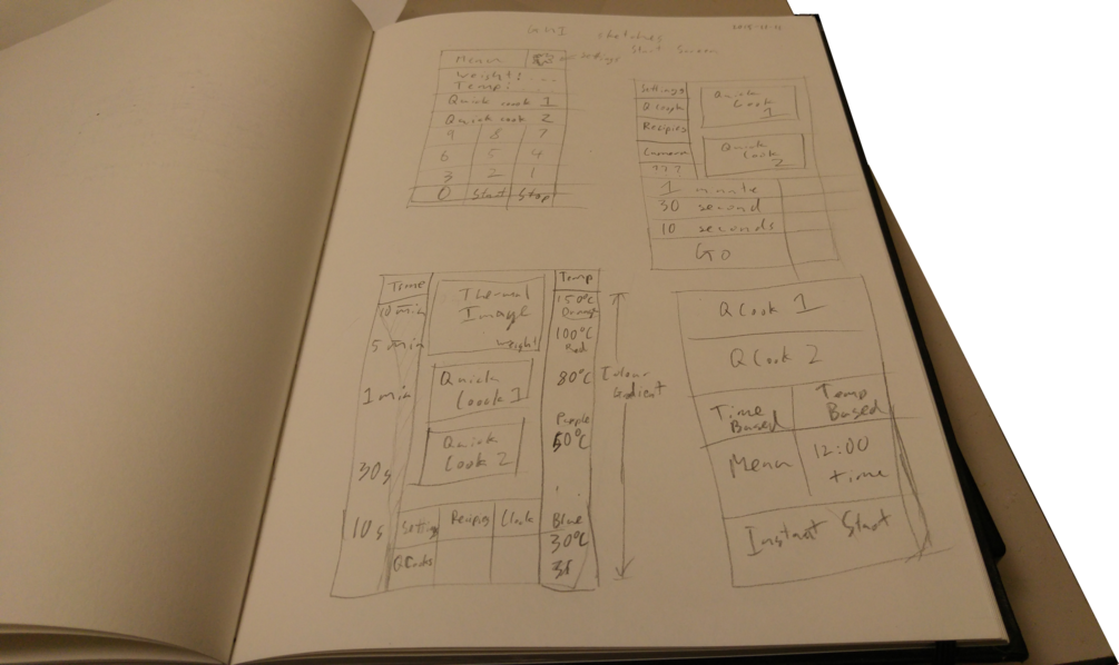
Everything else, most of the work, is to support and implement this improvement. As I am now up to playing with the screens, selecting screen sizes and touch interfaces it seemed worthwhile to spend a bit of time considering what the GUI will actually look like.
I did a few pages of pencil sketches, useful to work through a wide variety of ideas.
Then I did a prototype implementation in HTML to iterate the better ideas. This prototype is below, it is a fully interactive webpage – some bits pretend to work, other bits are stubbed out.
I would really appreciate it if people would play and give feedback. It is designed for a fixed screen size of 480×800 pixels, the primary user interface will be finger on a touchscreen, there will also be general web browser access for PCs and portable devices.
Teeing up a display for an embedded system is a little more complex than buying a monitor.
At the core of it is one of my favorite sayings, “The wonderful thing about standards is that there are so many to choose from.”
Starting from the screen end of things, I want a screen that is roughly 150x90mm in size. Because I want it viewable from the side and ideally all angles, I have a strong preference for an IPS display. I found a screen that is really nice, Topfoison’s 6″ IPS display.
This display uses MIPI DSI for its video signal, specifically a 4 lane MIPI DSI interface (because standards restrict choice too much many standards allow incompatibility within themselves).
MIPI DSI is an interesting standard, it is a mobile industry standard (Mobile Industry Processor Interface – pronounced lowercase as mipi, like nbn) which essentially specifies a number of half duplex SERDES links for throwing video around. Many mobile phones seem to have adopted the standard as it removes the need for a video converter – reducing part count/cost, simplifying cabling and reducing internal EMI. The display and chip manufacturers have shifted with the market. However as it is fairly new mostly it is new/expensive hardware with support.
If you are meant to be doing something else here is some further reading, nice overview, detail with pretty scope pictures.
So, looking at hardware to plug in to this we have:
BananaPi M1, the board I have been planning on using.
Is not listed as supporting MIPI DSI, does support relatively generic LVDS output.
Graphics processor is the ARM MALI400 MP2, the newer ARM MALI cores include a display controller but I believe this wasn’t the case for the MALI400. I haven’t been able to find documentation on what display controller Allwinner used in the A20 chipset.
Some websites do claim that BPI has a MIPI DSI output, I think they are wrong and are simply assuming that the RaspberryPi look-alike video header is a function-alike video header.
BananaPi M2
Uses the Allwinner A32s (datasheet) chipset which does not support MIPI DSI output.
The Allwinner A31 does, but it seems they removed it when pluralising chip.
The SinoVoip website lists the output as “LVDS/RGB/CPU display interface (DSI) for raw LCD panels” on the product page. However the DSI gets dropped when getting into the detailed LCD connection information.
BananaPi M3
Uses the Allwinner A83T chipset
Specifically states support for MIPI DSI and MIPI CSI interfaces, with dedicated headers.
However this isn’t available yet, when contacted SinoVoip suggested it should be out around the end of this year.
Raspberry Pi
The Raspberry Pi uses a Broadcom chipset which supports and has a header for 2 lane MIPI DSI output.
However due to driver issues this output isn’t generally useable.
There are complex projects made with custom hardware to convert the HDMI output to MIPI DSI.
The Raspberry foundation produced a screen which uses the MIPI DSI output with kernel support. Apparently they managed to do it in such a way that generic boards aren’t supported, just theirs.
Lemon Pi
Uses an Actions S500 chipset
Specification states support for MIPI DSI but doesn’t specify how many lanes and the S500 documentation doesn’t mention DSI.
Not yet available, indications that things are happening so may ship this year.
Includes (optional) built in bootable permanent storage.
Other boards
There are other systems out there which aren’t suitable for various reasons.
For example the H4 Hummingbird uses the Allwinner A31 with MIPI DSI output but at $70 isn’t competitive.
Making choices
I have ordered the official SinoVoip 7″ LCD touchscreen. This is a non-IPS 7″ display connected to the LCD connector via a dedicated adaptor board. It also includes a touchscreen, no details so am assume it is a capacitive panel. The main reason for getting this screen is that as it is distributed by SinoVoip it should be well supported, the price is rather high but I haven’t inquired about production quantities.
I am also negotiating an order of the Topfoison 6″ IPS screen with HDMI adaptor. The adaptor seems to add about $5-10 USD per unit and I expect a HDMI cable will be a few dollars, so the wiring ends up being a substantial percentage of the screen costs. Currently using MIPI DSI directly isn’t an option but I will definitely reevaluate down the track once the next generation of boards comes out.
When selecting a touchscreen there is actually an interesting choice that I have to make. There are two common touch technologies, resistive and capacitive, many people probably know it as old and new touchscreens. (Interesting aside, capacitive screens actually came first in 1965 but weren’t widely adopted, then resistive screens became common before capacitive screens resurged with phones and became the “new” style.)
Resistive screens
A resistive screen works by letting you push one side closer to the other and detects this change.
Will work if wearing gloves, using elbow or poked with a stick.
Plastic is scratch resistant.
Can optionally detect pressure.
Con:
Easier to damage screen.
Damaged screen is useless, minor damage typically causes complete failure.
Only supports two simultaneous touch points.
Capacitive screens
A capacitive screen detects power loss to a nearby conductor such as a finger. The modern standard is a projected capacitive technology (PCT) panel which means a direct touch isn’t required, this allows a protective glass layer to be inserted on the top of the screen assembly.
Pro:
More familiar to people.
Easier to clean.
Sensitive PCT devices can detect fingers through insulating gloves.
Supports complex multitouch patterns.
Con:
Fails if coated in a conductive material, such as sweat or food liquids.
Sensitive to mechanical design, the metal chassis is a conductor which can significantly impact on screen operation and sensitivity.
Conductivity varies on the person, the person’s hydration, ambient humidity etc.
Further pontificating
So for something portable, like a phone, going capacitive is obviously the better choice.
For a kitchen appliance it is far less clear. Wearing dishwashing gloves or smearing tomato sauce across the controls is going to be more common.
The big factor I keep coming back to is the familiarity. People expect to have a solid capacitive touch screen and attach a higher quality value to it than a resistive screen. And that the limitations of the capacitive screen are well understood so people seem happy to work around them.
Basically the engineer in me leans towards resistive, the marketing orphan I recently adopted says capacitive.
So for now I’m getting both. I am already familiar with capacitive touch panels and have one coming as part of one of my screens. So I just need to acquire a resistive panel to play with and understand.
Shopping
Buying a resistive panel is far harder than it should be… mostly due to limitations with the wondrous site alibaba.
<rant>
Alibaba is fantastic for interacting with component suppliers but the search engine is absolute rubbish, pre-Google Yahoo rubbish. (As Yahoo used to own a substantial chunk of Alibaba maybe it is literally the pre-Google Yahoo rubbish.) Essentially you enter some words, Yahoo searches for those words in the title of each product, the product with the most words in common is the top of the list. Which means that the retailers create new duplicate product entries with different titles trying to hold the bingo card that matches your search words. One touchscreen manufacturer had a single 4 wire resistive touch product, available in about 15 different sizes. They had roughly 1800 bingo cards/product entries trying to attract eyeballs.
(A nice trick with Alibaba direct is that they don’t keep these all updated, so you can often get up to 20% off by finding a differently priced entry of the same product from the same manufacturer.)
Once I find a manufacturer I try to figure out if I can trust them. A warning trigger for me is anything that they are obviously lying about in their marketing, if there are obvious lies I can see then there are probably subtle lies that I can’t and will bite me later. With resistive touchscreens however EVERYBODYalmost everybody lies, possibly this is related to the above Alibaba is crap rant. And it doesn’t look like lies that help them, a 4 wire touchscreen has four analog passive resistive wires, they state this, then in the interface section they state “RS232 or USB interface”… which I don’t understand. It clearly is a 4 wire FPC connector, there is no RS232 or USB plug in the picture, no mention in the description. I suspect there is a series of checkboxes box for interface and they feel the need to tick something… Another odd one is they list a resolution, numbers vary but all are wrong. It is an analog device, any resolution limitations come from the quantization performed by the controller, which they don’t sell. Why provide a fake number and risk it being smaller than somebody else’s fake number when the real answer is infinite and therefor better? sigh
</rant>
Buying
I have reached out to three suppliers for further information:
So for the more recent substantial chunk of time I have been neglecting this project, mainly procrastinating by playing with Zookeepr code. Over the last month I’ve churned almost 20k lines of code, though not all committed yet. Which is a relatively productive way of being spectacularly unproductive.
The big news is that I was selected to speak at the next linux.conf.au. I confess this was a bit of a surprise, my long term plan was to submit proposals to a few venues this year and hopefully speak in 2017. Spectacular success on that front does change the microwave plan slightly as it commits me to having a demonstrable prototype – so I’ve shifted my project reevaluation point further down the game plan and split the prototype section into two halves with an evaluation point between the cheap and expensive halves.
To support this shift I have restructured my plans around the basic prototype. I have set the final vision and the order of steps to achieve it.
As the base I will use a Panasonic NN-SF550W Microwave, this is a basic microwave that features an inverted power supply and magnetron as well as a flatbed and stirrer. I will replace the display with a screen and touchscreen, the processor with a banana pi. The power supply and door sensors will be integrated with the processor. Both the Panasonic Grid-Eye and Seek Thermal cameras will be mounted into the roof, I may only connect one at a time. A set of scales will be built into the floor of the microwave, probably using the existing base plate. Software of some sort will tie all the components together though it may not be pretty.
Work plan
At a rough estimate I’m looking at 2-3 months work to get a feature complete franken-prototype. There is also significant delay time in there to acquire new components to play with.
The groups of work are:
Screen
Touch
Scales
SeekThermal
GridEye
Inverter
Other electronics
OS Software
The Gantt chart below breaks it out into a bit more detail with some rough timing. I have only staggered out the next two weeks because I expect predicting that far out is ambitious, further would be silly.
I’ve also used a different program to generate the gantt chart with a different style of export, trying out Gnome Planner instead of Gantt Project. I confess I don’t really like either of them.
One of the thermal imagers I have been considering using is the Seek Thermal camera. An impressive camera, currently only available in the US, they use a Raytheon sensor to create a small USB camera designed to be used with a mobile phone. Most importantly for me it supports a wide range of temperature, an intentional limitation with the FLIR cores.
Sadly the camera has some issues. All thermal sensors require post-processing to clean up the image and work around quality issues with the image, it is a bit more complex than a standard CCD. The Seek camera does some basic processing in the device but most of the image manipulation required to get the camera working is performed in the Android application. Seek has been promising an SDK since the product was first announced, presumably this will allow other clients to be used, but no SDK has been forthcoming.
I have been spending a fair bit of time trying to understand how to use their factory calibration values and get a good temperature reading out of the device, so far unsuccessfully.
As a side effort I spent a bit of time working on another problem with the device, with more success.
When first released the camera had an erroneous thermal gradient at the edges and particularly the corners. This was particularly obvious if you pointed the camera at a thermally flat surface, such as a wall, the autoscaling would highlight the error as the only variation in the image. Various people reported that adjusting the lens holder helped and that the problem varied with time. I believe that the issue is a combination of the lens holder being imperfectly aligned and so its temperature influences the sensor, the lens holder is heated by the circuitry around it and so gets worse with time.
Early this year Seek corrected the problem with a software update. Looking at version numbers of each component it was clear that the fix was purely post-processing performed by the Android application. They have never responded to questions on how this was achieved.
I have managed to figure out their technique and have documented it in an Octave/Matlab function which reproduces the process used. Hopefully this will allow people making independent clients to apply similar corrections and allow the camera to be used with non-phone devices.
I discuss details of the technique on the eevblog forum where most of the Seek dissection has taken place. The script is also relatively simple and commented for anyone with Matlab experience.
Some before and after photos of the processing. A thermally flat image and some ugly face.
Before – Floor
After – Floor
Before – Face
After – Face
It is interesting to see that the corrections to the face go far further than I initially expected.
The fixup in the bottom right corner is obvious, the gradient gets changed to a flat background.
However the fixes around the bottom of my face were startling, my neck gets corrected to a much better temperature, the beard cools down and the jumper collar cools right off. I think all these revised details are more accurate.
Source code, including the raw data of my face and usage instructions, is on github.